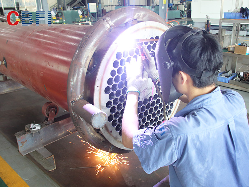
An ice-making system tube ice making machine, including a compressor, an oil separator, a condenser, a liquid reservoir, a filter dryer, an ice-making liquid supply valve, a de-icing liquid supply valve, an oil return solenoid valve, a throttle valve, and a tube The ice ice maker, gas-liquid separator and oil return pipe are characterized in that: the compressor exhaust pipe communicates with the condenser and the accumulator through the oil separator; the accumulator liquid supply pipe There are two flow channels. One flow channel passes through the filter drier, the ice-making liquid supply valve, and then is connected to the inlet of the tube ice ice maker through the throttle valve, and the other flow channel is connected to the ice-making tube through the de-icing liquid supply valve and the tube ice maker. The other inlet of the tube ice maker is connected; the pipeline at the outlet of the tube ice maker is connected to the compressor through a gas-liquid separator. The utility model has strong practicability, simple and firm structure, large processing capacity, stable working performance, and convenient cleaning , High cost performance, easy to install and use, environmental protection and other advantages.

Evaporator for tube ice maker machine
The evaporator for the tube ice making machine includes an evaporator body. The inner cavity of the evaporator body is uniformly provided with an ice making tube, and the ice making tube is evenly provided with a cutting device. The left side of the left cutting device is provided with a piston rod and a piston The left end of the rod penetrates the left side wall of the evaporator body, and the left end of the piston rod is provided with a pulling device, and the inner cavity of the support frame is movably provided with a connecting plate, and the right end of the pull rod is fixedly connected with the left side wall of the connecting plate. By changing the docking relationship between the openings at different positions and the ice-making tube, the inner cavity of the ice-making tube is partitioned by the partition, and the entire inner cavity of the ice-making tube is cut into several sections and the cut-off length is controlled to realize the change of the ice-making length. The ice does not have to be cut, thereby ensuring the quality of the ice.
Separating disc for tube ice maker
The separating disc for tube ice machines includes a mounting rim, a mounting sleeve hole is provided in the center of the mounting rim, a spoke one is provided on the outer wall of the mounting rim, and an inner rim is connected to the other end of the spoke one, The outer wall of the inner rim is provided with two spokes, the other end of the second spokes is connected with an outer rim, and the front side of the inner rim and the outer rim is provided with a water groove, and the tube ice is combined with the spokes one and the second spoke. The crushed ice and water are separated to prevent the crushed ice from blocking the separation hole and cause the water to be separated from the tube ice. The rotation direction of the spoke 1 and the second spoke is opposite to ensure that the water will not be with the tube ice when the separation disc is rotating. It is discharged from the ice discharge port to ensure the dryness of the tube ice.
Heat exchange tube for tube ice factory
The heat exchange tube for a tube ice plant includes a first branch tube, one end of the first branch tube is fixedly sleeved with a first tube seat, one end of the first branch tube is connected to a second outer branch tube, and one end of the second outer branch tube is fixed on the outer wall A second pipe socket is sleeved, an L-shaped connecting block is provided on the second pipe socket, the outer wall of the second pipe socket is rotated to connect a threaded sleeve, and the other end of the second outer branch pipe is movably connected with the sleeve, the sleeve The inner cavity of the tube is provided with a second inner branch, the annular groove is equipped with a return spring at an equal interval, the notch of the annular groove is provided with a limit block inward, and the outer wall of one end of the sleeve is fixedly connected with a pipe sleeve, the The tube sleeve is rotatably connected to the fixed seat, and the present invention has the advantages of easy disassembly and assembly, shortens the length of the heat exchange tube, reduces the difficulty of cleaning, is convenient and quick to use, and improves the work efficiency of the staff.